This article explains the various causes of premature failure of power factor capacitors and presents some best practices to extend the useful life of AC Power Factor Capacitors. In order to understand capacitor failures, it is helpful to first understand a bit about capacitor construction.
Prior to 1980, power factor capacitors were produced with Chlorinated Biphenyls (PCBs), which was a compound with good dielectric properties, heat transfer capability and stability over a wide temperature range. Although they were later deemed to be hazardous to health, at the time, they were the best available to do the job. These capacitors also used aluminum foil as winding material and paper insulation. This provided a very robust capacitor that could withstand harsh electrical environments.
The ban on PCBs led to the search for and ultimate adoption of newer technologies in materials as well as production techniques. Today, most (low voltage) power factor capacitors are constructed using metallized polypropylene. Polypropylene is a thermoplastic material with a melting point generally between 130C and 170C. Instead of aluminum foil, the electrical plates are formed by spraying a metalized coating onto the polypropylene film.
Many good characteristics such as self-healing and increased power density resulted from the adoption of this new metallized film technology. The self-healing benefit of metallized film capacitors is a great advantage which enables the capacitor to clear small internal faults which may be caused by voltage transients, and enable the capacitor to go on working for many more years. However, the use of plastic film also makes the capacitor vulnerable to both electrical and environmental conditions. Capacitors should be thought of as sensitive electronic components, not in the same temperature categories as transformers and reactors.
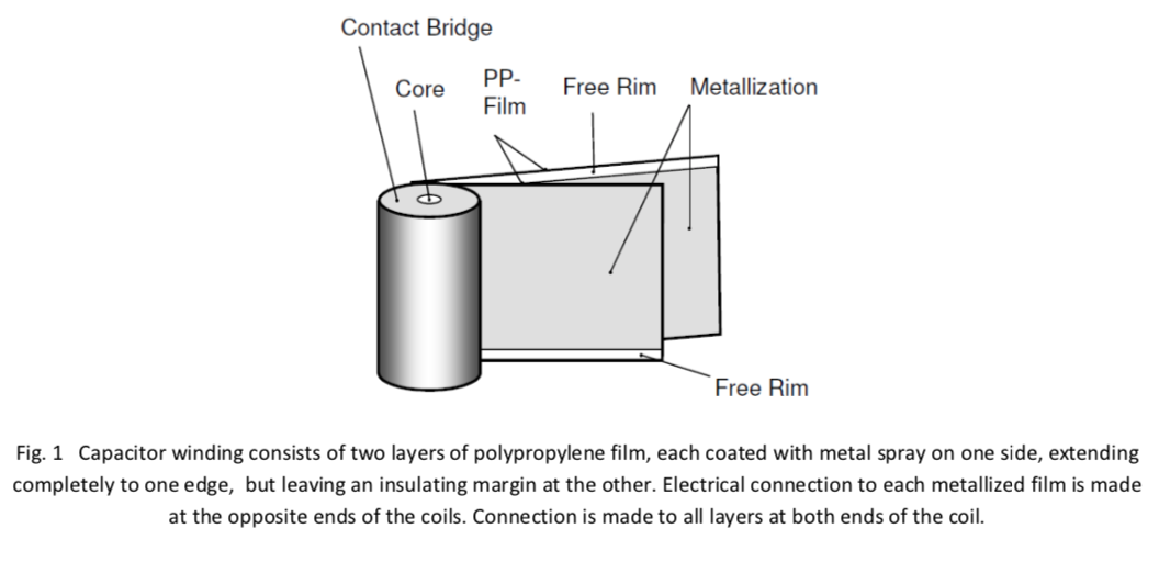
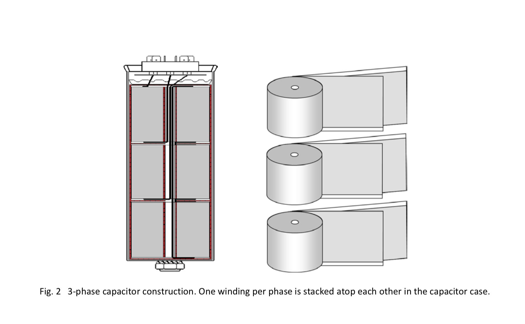
Metalized polypropylene film has the unique capability to heal itself in cases where a dielectric breakdown occurs in the winding. This might occur due to transient over-voltages or microscopic imperfections in the dielectric material. When a short circuit occurs, due to dielectric breakdown, the metalized coating is vaporized around this area, leaving an insulating margin surrounding the failure point. Since voltage is applied at the edge of the entire winding, a self-healing event can experience a flow of energy from every direction throughout the winding to the faulted area of the film. If a dielectric breakdown is not quickly healed, then due to localized heating cause by the fault, the film can lose its dielectric properties through melting and the failure can spread to multiple layers. There is no direct means to limit the energy flow which may result in catastrophic failures of capacitors.
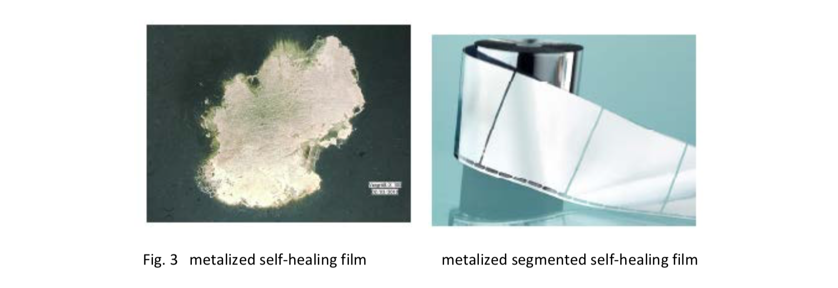
Multi-layer events that can cause catastrophic failures, are virtually eliminated when segmented film is used. With segmented film, voltage is applied to the winding at the top and bottom edges, however, current flows
into the individual segments from only one direction. All current passes through the fusible links which by their impedance naturally limit current into the segment. If a segment experiences a dielectric failure that is not quickly healed, the links for that one segment will open and isolate the damaged segment.
Capacitors are often thought of as the same category of electrical equipment as transformer and reactors. They are very different. Capacitors are actually electronic devices having significantly lower temperature capabilities and electrical insulation properties than either transformers or reactors. Three prominent factors that cause early failures of AC capacitors used in power factor or harmonic filter systems are: excessive voltage, excessive current and excessive temperature. The temperature rise of a capacitor is a function of the total internal watts dissipated by the windings. Initially, the watts are due to fundamental current (squared) and equivalent series resistance of the windings (ESR). For this, the geometry of the capacitor windings plays a major role. Additional heating will be produced when harmonic currents flow into the capacitor and when capacitor terminal voltage increases (due to system voltage fluctuations, reactor boosting effects, or due to higher current flow). Voltage transients, sustained over-voltage, transient currents, sustained over current, and ambient air temperature all may affect the performance and life expectancy of power factor capacitors.
Excessive voltage may be due either to transient events or sustained swells and over-voltages. Any of these may have an effect on capacitor life.
This may be the result of lightning, a utility system event such as capacitor switching or fault clearing, or even a switching event such as capacitor switching within a facility. Other than for lightning, the magnitude of these transients is often limited to about 2 p.u.. In the case of lightning induced transients, it may be higher. Characteristic of a transient, is a high peak voltage with a steep rise time (high dv/dt). Depending on the magnitude of the transient over-voltage, a dielectric breakdown can occur between two layers of the capacitor winding, leading to a “self-healing” event in the capacitor. If the breakdown is managed through self- healing, then the capacitor may go on living without a recognizable change in its performance characteristics. In the case of a severe transient, the dielectric breakdown may affect multiple layers and result in a complete failure of the capacitor. If the internal short spreads slowly, then the internal overpressure disconnector may safely interrupt the capacitor. If not, then the capacitor may burst. This is where capacitors which are constructed using segmented film have an advantage over typical capacitors. Capacitors that are constructed with segmented film have extra protection against multi-layer breakdown and case rupturing by limiting the energy into the faulted area of the metallized film.
There are a number of reasons why capacitor terminal voltage may be elevated, including supply voltage tolerance (5% per ANSI C84.1), light transformer loading, boosting effect of capacitor and inductive reactance, harmonic resonance. In some cases, the peak voltage may increase disproportionately compared to the rms voltage. This is because voltage distortion is most predominant at the peak of the waveform.
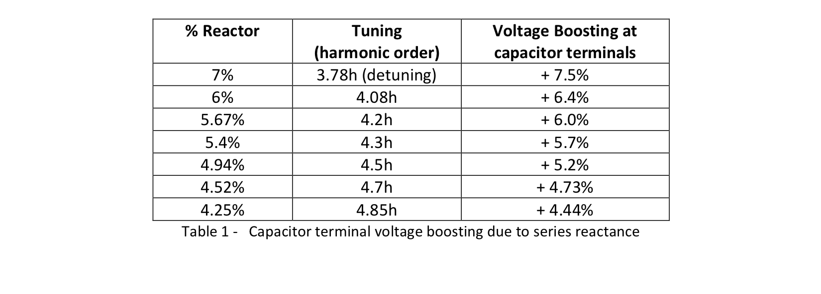
Any time there is inductive reactance in series with a capacitor, terminal voltage will be boosted. Some reactance is always present due to the service transformer. Additionally, when a capacitor system includes a reactor for either tuning or detuning, this will also increase capacitor terminal voltage. Any time a reactor is included in series with a capacitor, the capacitor voltage rating must be increased to accommodate the voltage boosting that occurs naturally. For example, a capacitor used with 7% detuning reactor requires a continuous voltage rating of at least 516V. The expected voltage boosting is indicated in Table 1.
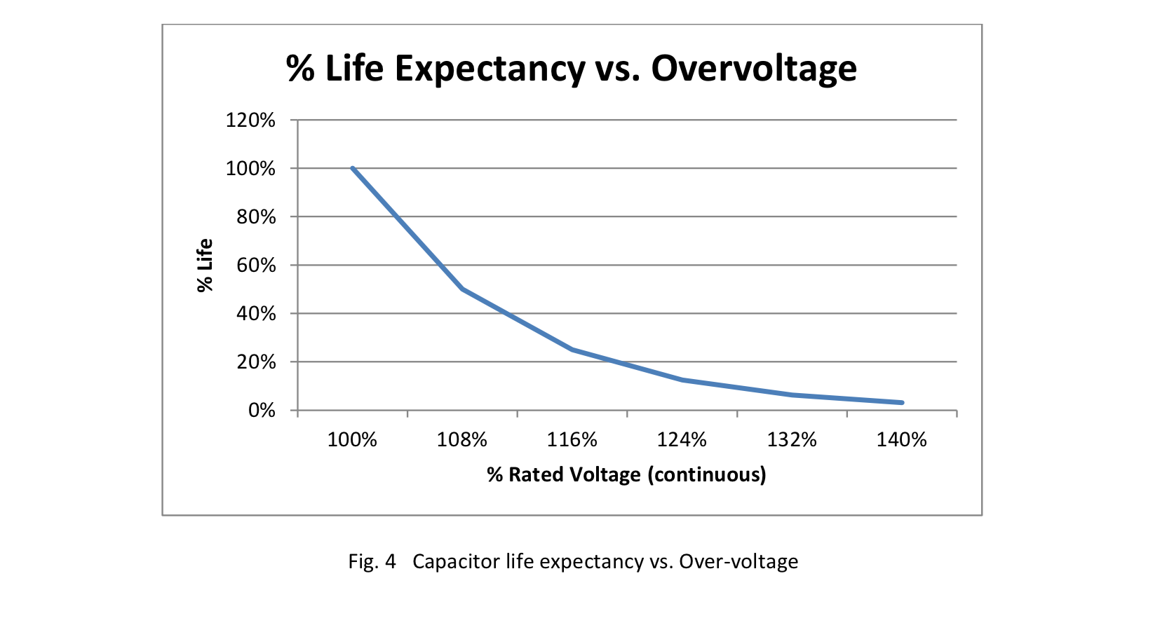
Sustained over-voltage can degrade the dielectric system in a capacitor, increase internal losses and temperature ultimately causing premature failure of the winding layer insulation. When capacitor terminal voltage is high, more current flows into the capacitor, causing increased heating. If the capacitor is operated continuously with over-voltage, then its life will generally be reduced according to the life expectancy curve in Figure 4.
Both transient and steady state over-current can take their toll on capacitor life. Each can cause premature aging of the dielectric system resulting in reduced life expectancy.
Capacitors can experience high transient currents during switching. Like a motor or transformer, there is an inrush current associated with the switching of capacitors. They can experience inrush current when they themselves are switched ON, and they can experience outrush current if a nearby capacitor is switched ON. Capacitor inrush current can be minimized either by using contactors with pre-insertion current limiting resistors, or by having a reactor in series with the capacitor. Capacitor life is typically specified with reference to the number of switching events per year ( ie: 130,00 hours life with up to 40,000 switchings per year). Stronger capacitors may have long life with as many as 40,000 switchings per year.
The steady state current in a capacitor will increase above the expected fundamental current when there are harmonics on the system, when the system voltage is elevated and under harmonic resonance conditions. The capacitor’s reactance (ohms) decreases for higher frequencies, therefore, they can be a low impedance path for harmonic currents. Due to their low ohms at harmonic frequencies, a small amount of harmonic voltage may cause large harmonic currents to flow in a capacitor. Increased current in a capacitor causes the capacitor terminal voltage to increase and produces more internal heat based on current squared and ESR.

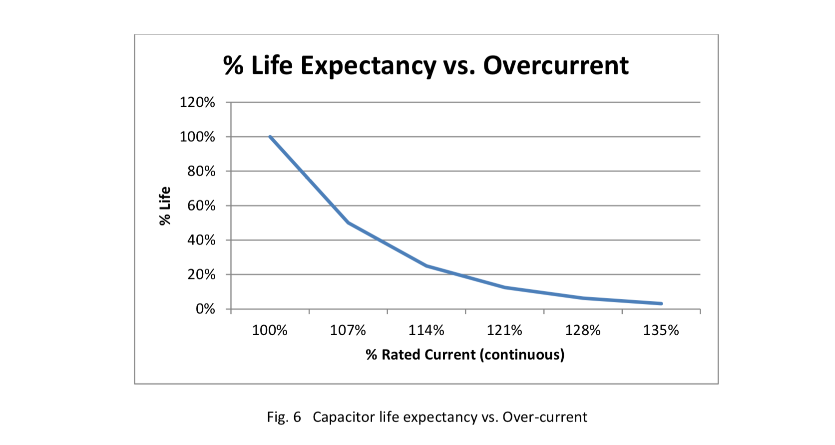
Sustained over-current will increase capacitor temperature rise leading to degradation of the dielectric system and accelerates the aging process. Additionally, when capacitor terminal voltage is high, more current flows into the capacitor, causing increased heating. If the capacitor is operated continuously with over-current, then its life will generally be reduced according to the life expectancy curve in Figure 6.
Heat is known to be a killer of electronic components. This is also a major cause of capacitor failures. Over voltage and over current both increase the internal temperature of a capacitor and lead to reduced life. Surprising to many, the geometry (diameter vs. length) of the capacitor windings has very much to do with the internal temperature rise of a capacitor. Based on its own internal heat generation, a capacitor may face strict limitations in the ambient temperature within which it may be applied. Ambient temperature in the case of capacitors does not refer to the room air, but rather to the temperature within the capacitor enclosure. That is the air immediately surrounding the capacitors. In many cases, this can be 20°C above the ambient room air temperature.
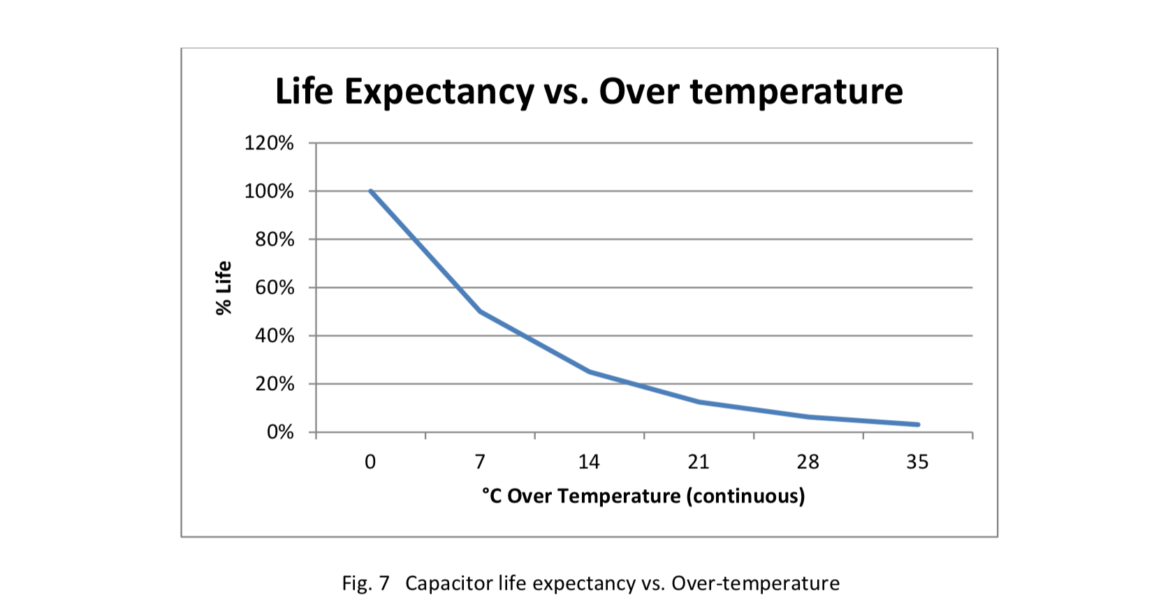
Additionally, placement of a capacitor into an environment that exceeds its continuous temperature capability can shorten its life dramatically. Continuous operation of a capacitor in an ambient temperature that is 7°K above its rated temperature will reduce its life at least by 50%. For each seven degrees Celcius (7°C) above its rated operating temperature, the capacitor life is reduced 50%. Typical capacitor life reduction due to elevated ambient temperature is illustrated in the Figure 7.
Unfortunately, some capacitor temperature ratings can be misleading. Some have ratings printed on their nameplate that state 55°C max, however, they are actually only capable of use in an environment that is 45C maximum average for 24 hours and 35°C maximum as an annual average. This rating method is based on IEC 60831-1:2014, Table 1 [Letter symbols for upper limit of temperature range]. If a capacitor is rated -40/D, 55°C max, then it is suitable for use in an enclosure where the internal air does not exceed 35°C as an annual average and 45°C as a daily average, with the short term temperature never exceeding 55°C. The IEC standard however, does not define the duration of time for which the capacitor is capable of operation at the maximum temperature (55°C). Table 3 below illustrates the meaning of common capacitor temperature classes. In some cases, data sheets for capacitors using this rating method include derating charts for ambient temperature. When selecting a capacitor, make sure that it has a continuous ambient temperature rating that is sufficient for your application. Stronger capacitors have continuous ambient temperature ratings as high as 60°C.
The physical construction of capacitors has much to do with how much internal heat they generate (and how they will perform in elevated ambient temperatures). Capacitance is a function of the area of two conductive plates (films) that are wound together with a small insulating space between them. If a capacitor is wound with a wide strip of film, then it will take fewer turns to achieve a desired area than if the capacitor is wound with a narrower strip of film. It would be less expensive to wind the capacitor with the wide strip of film (tall winding), than with a narrow one (short winding). However, the internal heat generated by the winding is much different.
A study of capacitor internal heat generation, reported in IEEE Transactions on Industry Applications [1] revealed that for a given capacitance and winding area, short windings of larger diameter generated far less internal temperature rise than tall windings. The article compares four capacitors with equal uF, voltage rating, film thickness and thickness of metallization thickness. The only difference is the height of the four capacitors.
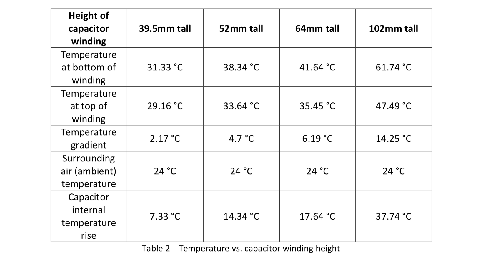
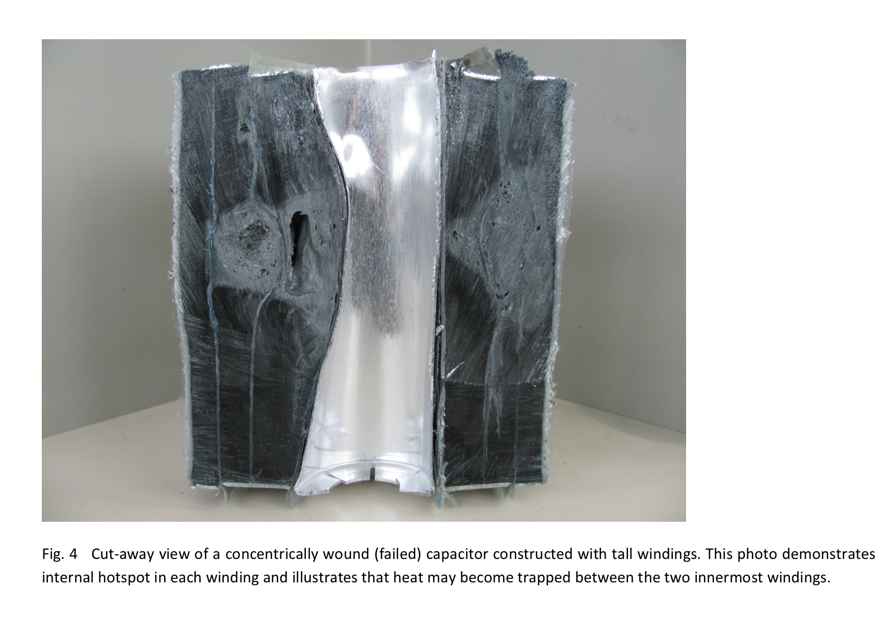
The conclusion was that the optimized winding construction for capacitors is a short coil which results in a relatively larger diameter. Although it may be less expensive to produce capacitors with tall windings, they do not handle heat as well as short windings. The shortest capacitor (Table 3) not only had the best and most consistent temperature distribution within its winding, it also had the lowest internal temperature rise. Internal temperature rise varied from 7.33 °C (short capacitor) to 37.74 °C (tall capacitor). This means, that although tall capacitor windings are probably less costly to produce, since they require less winding time to achieve the necessary coated surface area, they operate at higher internal temperatures than short windings. This data shows a difference of 30°C internal temperature rise between short and tall windings. Given they are all constructed with polypropylene, it is obvious that the short windings will handle higher ambient (surrounding) air temperature than capacitors with tall windings. Having lower ESR and internal temperature rise, the short capacitor will generally be capable of handling more current. Capacitors made with tall windings, may have poorer heat distribution than short windings. Concentrically wound capacitors can also generate more internal heat with the possibility of trapping heat between two windings. They can experience internal heating due to two reasons, 1) heat becoming trapped between inner most and middle winding, 2) tall windings experiencing higher ESR, resulting in higher internal watts.
As with most electronic devices, heat is a major factor that leads to premature failure. All of the factors discussed previously in this paper, induce extra heat in the capacitor. Whether it is over-voltage, over-current, or poor construction technique, all can increase the internal temperature rise of the capacitor and lead to shortened useful life.
One would think that talking about ambient air temperature would be a straight forward topic. But in many cases, it really is not. Unfortunately, there can be ambiguities in the data available to many capacitor customers, leaving too much to interpretation. For example, in many cases, a maximum ambient temperature rating does not define the maximum continuous temperature the capacitor can handle. One common method that manufactures use for specifying ambient temperature capability of a capacitor is the IEC 60831-1 temperature categories. Capacitors in this standard are classified in temperature categories where each category is specified by a number followed by a letter. The number represents the lowest ambient air temperature at which the capacitor may operate. The letters represent the upper limit of temperature variation ranges, having the maximum values specified in Table 3, below.

Table 3 above is based upon service conditions in which the capacitor does not influence the ambient air temperature, such as outdoor applications. When the capacitor is used within an enclosure, then the ambient temperatures in Table 3 would refer to the air surrounding the capacitors. Depending on enclosure and system construction, the air inside the enclosure may be 20°C higher than the room air temperature (or outdoor air temperature). This type of specification makes the assumption that temperature will vary during the capacitor’s use, and that the range can go (temporarily) as high as the maximum, but not for any specified length of time. In fact, some capacitors with this type of rating system, have derating curves that must be applied based upon the expected ambient (surrounding air) temperature.
It is fairly common to see capacitors with rating of -40/D and those capacitors often state 55°C max. This means that the capacitor may be operated at -40°C. It also means that capacitor may be used in an application where its surrounding air temperature never exceeds 55°C, and that a 24 hour average does not exceed 45°C and a one year average does not exceed 35°C. However, the table does not provide an indication as to how long or how often a capacitor may be capable of operating at the 55°C maximum. The safest approach is to remove the ambiguity by selecting a capacitor with a clearly defined maximum continuous ambient temperature capability (ie: 60C maximum continuous ambient temperature).
Bibliography
[1] Thermal Simulation for Geometric Optimization of Metallized Polypropylene Film Capacitors, M.H. El- Husseini, Pascal Venet, Gerard Rojat, and Charles Joubert, IEEE Transaction on Industry Applications (May/June 2002)
[2] IEC 60831-1, International Standard, Shunt power capacitors of the self-healing type for a.c. systems having a rated voltage up to and including 1000V. Part 1: General – Performance, testing and rating – Safety requirements – Guide for installation and operation.
Author:
John Houdek
Allied Industrial Marketing, Inc.
W67 N222 Evergreen Blvd., Suite 209 Cedarburg, WI 53012
Phone: 1-262-618-2403
Website: www.alliedindustrialmarketing.com
Our team at the PQMC Store is here for you. For all inquiries, please do not hesitate to contact us. Our customer service team will contact you promptly.